What's new

iPad 2 DIY Charger

Question: since I am thinking about using a 8 amp power supply do we need to regulate the power going to each usb port / dock connector? I know that the Ipads draw 2 amps each, and each iphone draws 1 amp each for a total of 8 amps.

Ken
:)

I would regulate the amperages for each connection. Just would probably be better for the devices.
Just my preference. I don't think there would be much of a difference though.
 
Last edited:
I would regulate the amperages for each connection. Just would probably be better for the devices.
Just my preference. I don't think there would be much of a difference though.

Graywolf,

Thank you for the recommendation, that was what I was thinking especially since I will also be plugging in ipods into the locations that I make for the iphones.

I see you are in Raleigh, NC, I just flew back from their on Wednesday of this week.

Ken
 
Graywolf,

Thank you for the recommendation, that was what I was thinking especially since I will also be plugging in ipods into the locations that I make for the iphones.

I see you are in Raleigh, NC, I just flew back from their on Wednesday of this week.

Ken

Weather is really nice isn't it? :)
 
I would regulate the amperages for each connection. Just would probably be better for the devices.
Just my preference. I don't think there would be much of a difference though.

Ok so how do I regulate current efficiently?
And how do I build it into Tim's circuit?
I am now wondering if I can use a smaller power supply? I originally was going to use 5V, 5A, 25 watt power supply but this is to small based on my calculations. So i think I will keep the power supply that I mentioned earlier. I know that not every time every space on my charger will be filled but at night I could be easily charging 2 iPads and three iphones at the same time.

I saw on a circuit website that you can use at JFET current regulator but I don't know if this is the right device to use. On another site I saw the use of transistors to do the same thing. The key to the design that I want to make is small, compact and efficient.

The other thing that I would really like to add is a way to introduce led's into the circuit. So that when a device is pluged in a led light comes on and when the device is fully charged the led light goes out. This is not necessary for my first design but this is a wish for future designs.

I am not an electrical genius, so I have no idea how to regulate the amperage for each device besides using a separate power supply for each device. (which defeats the purpose of the small charger you have in mind)

As for the LED, I don't think it can be done. You would have to build another device for each iPad/iPhone that can tell the difference between fully charged and charging.
In theory, when the device is fully charged, it won't be pulling the same voltage and amps as it does when it is charging. So, if you could build a device that could tell the difference, it could be possible.

But this is just me speculating.
 
No need to regulate current to each device. Each device will draw the current it needs. Just make sure your power supply can accommodate the total current needed It is as simple as 5vdc through the USB cable outer pins and the voltages that I show on the inner pins of the USB.

Keep in mind that there is a tolerance on the 5vdc for USB. I am not sure the exact number but it can vary +/- somewhat and still work properly in spec. Typically +/-5% in industry. You should be able to look this up in Wikipedia.

The lambda power supply will do it but 8A may be a bit overkill. Double check the current draw on your devices. I believe the iPad only draws 2A when it is powered on and charging at the same time at full brightness. Getting a bigger power supply won't hurt you but streamlining this may save you some $$$$$.

Now that I understand your goal, then I agree a separate PS will make the most sense. Keep in mind that the PS will get hot when pumping out a full 8A. If you use a circuit board to make this neater, make sure the trace width and thickness is enough to carry the current that will travel on each trace.

Tim
 
timothyb1969 said:
No need to regulate current to each device. Each device will draw the current it needs. Just make sure your power supply can accommodate the total current needed It is as simple as 5vdc through the USB cable outer pins and the voltages that I show on the inner pins of the USB.

Keep in mind that there is a tolerance on the 5vdc for USB. I am not sure the exact number but it can vary +/- somewhat and still work properly in spec. Typically +/-5% in industry. You should be able to look this up in Wikipedia.

The lambda power supply will do it but 8A may be a bit overkill. Double check the current draw on your devices. I believe the iPad only draws 2A when it is powered on and charging at the same time at full brightness. Getting a bigger power supply won't hurt you but streamlining this may save you some $$$$$.

Now that I understand your goal, then I agree a separate PS will make the most sense. Keep in mind that the PS will get hot when pumping out a full 8A. If you use a circuit board to make this neater, make sure the trace width and thickness is enough to carry the current that will travel on each trace.

Tim

Timothy,
Thank you for letting me know that i don't need to regulate current.

So let me understand this correctly :
1) Since I am using a power supply I don't need to use the voltage regulator that you had in your circuit.
2) I can used your resistance part of your circuit in one of two ways:
a) create one circuit and wire it to each of the usb connectors
b) create 6 circuits one for each usb port.

Am I correct in what i am stating?

Based on your EE knowledge which method would you take?

In a earlier email you spoke about building the power supply into the unit, how hard would this be? could we make it rather small?
 
Killerken said:
Timothy,
Thank you for letting me know that i don't need to regulate current.

So let me understand this correctly :

1) Since I am using a power supply I don't need to use the voltage regulator that you had in your circuit.
That is correct. A fuse for each device would not be a bad idea. I.e. 3A fuse for iPad, 1A fuse for iPhone. This is just to protect against an accidental short circuit like dumping water on connector etc.

2) I can use your resistance part of your circuit in one of two ways:
a) create one circuit and wire it to each of the usb connectors. That is what I would recommend since these circuits should have negligible current draw. 1/4 watt resistors should be fine.
b) create 6 circuits one for each usb port. This is not necessary.

Am I correct in what i am stating?

Based on your EE knowledge which method would you take?

In a earlier email you spoke about building the power supply into the unit, how hard would this be? could we make it rather small?
Problem is current vs size. If you decide on a 8A power supply then the PS will be large. I think sticking with your idea of a inline power pack you can lay on the floor behind would be best. Then just buy a thru mount pc board style plug to detach the PS from the PC board for transport, etc. That is how I would do it. You could consider building the PS onto the board if you made a separate board for each device so you could locate them in different areas.

Other Suggestions:
1> bread board your circuit with the PS to verify all is working as expected before spending money on the final PC board.
2> Before you hook your iPhone or iPad up, double check the voltages on the 4 pins. Check them again once device is plugged in. That is check them each under full load to insure your 5vdc is being maintained

See my comments above.
 
Tim,
thank you very much for the quick reply. I ordered everything today so hopefully I should have everything in about 5 business days.

I now need to start designing and building the physical dock.

Ken
 
\@ timothyb..
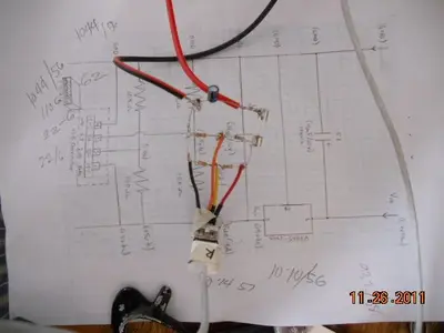
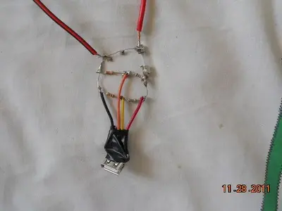
good day! im a newbie trying to experiment here. i followed your drawings and managed to charge my ipad2 at a rate of
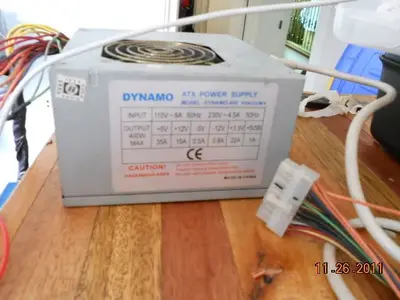
around 12- 15 % per hour versus around 25 % per hour charging of the original charger of ipad. i used and old atx power supply to get a 5v since i cant find a local supplier here in the philippines
that of 7805 with 2amps output.
my questions are:

1. when i measured that current im pulling from the atx power supply i got a reading of only around 500ma
is it this normal? or the source ( atx power supply ) cant supply the 2 amperes i need?
2. i tried to use the normal 7805, the cheap one, but the same result and it was very hot when i hooked it up
with the 12v output of the atx power supply.
does anyone know any replacement / or alternative to the old 7805? preferably a cheap one....
3. i have an old original sony psp charger that specified that it can give 2amperes of 5v
do you think this will increase the ampere of this circuit?

DSCN4327.webpDSCN4323.webpDSCN4329.webp
 
update:
i hooked it up with an original sony psp charger/adaptor 5v 2000ma/
got at 600- 660ma current which charges my ipad2 at a rate of 18% per hour

raffy/manila philippines /november 29, 2011

DSCN4333.webp
 
Tim,
I am wondering if you can help me.

I finally built the circuit board. I have 6 USB ports connected to the circuit board. The problem I have is as soon as I connect two ipads to the system the power supply shuts down. This is completely confusing me since I purchased a 5 volt, 8 amps, 40 Watts Max power supply.

Any ideas?

Also my voltage on my pins are a little different than yours even with using the same resistors.

Pin 1 = 5.2 V
Pin 2 = 2.091 V
Pin 3 = 2.976 V
Pin 4 = 0V

Please note it does not happen right away but it does happen 15 to 20 min later.

Any thoughts?
 

Most reactions

Latest posts

Back
Top